Subassembly Flow Systems

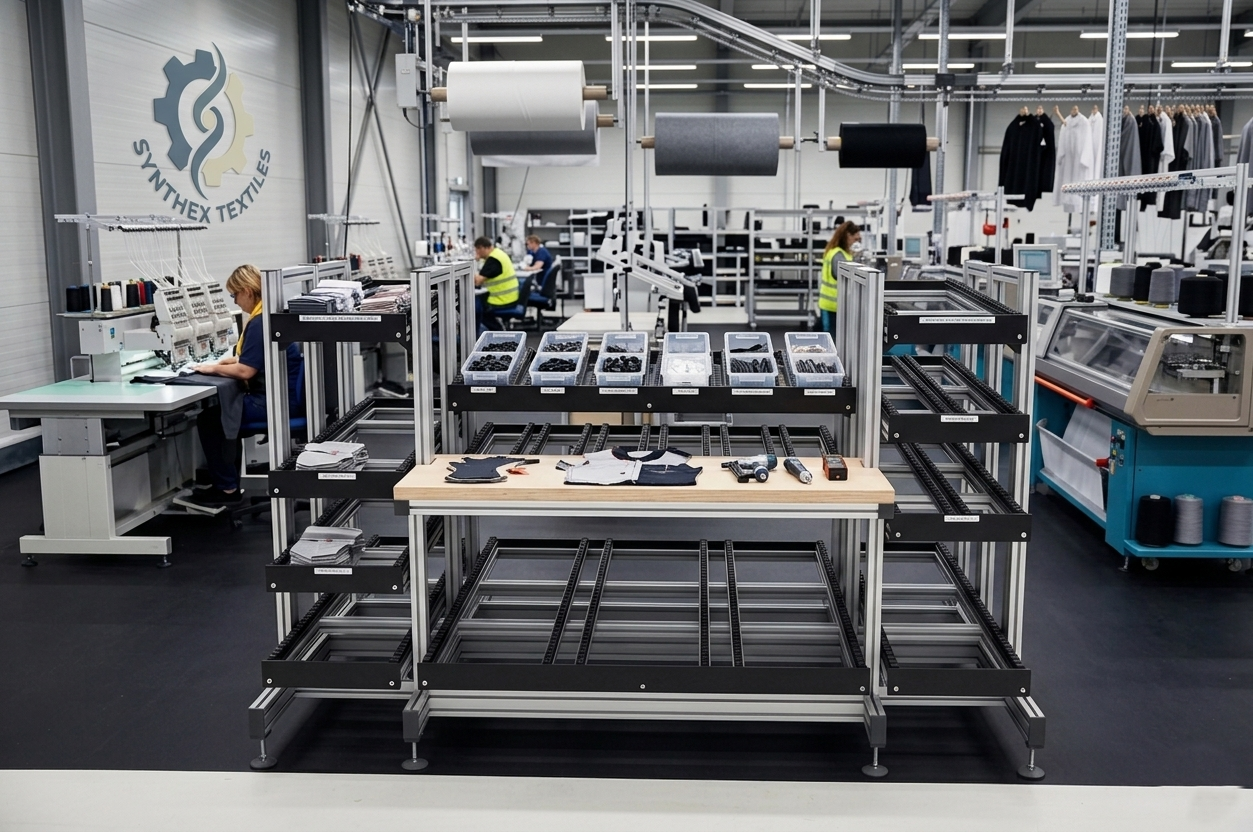
Subassembly flow systems connect feeder sub-assembly cells to main final assembly lines with gravity-fed FIFO lanes — eliminating WIP buffers, floor staging, and manual sub-assembly retrieval between processes. The sub-assembly cell loads completed units onto the rack rear; the final assembly line picks from the rack front in the exact production sequence.
Key Features

Feeder-to-Final Line Connection

Gravity-fed lanes physically connect sub-assembly output to final assembly input — no fork truck, tugger, or manual carry between processes.

FIFO Sequence Preservation

Rear-load, front-pick architecture ensures the final assembly line receives sub-assemblies in the exact sequence they were built in the feeder cell.

WIP Buffer Elimination

Lane depth sized to takt-time buffer only — excess WIP accumulation is physically prevented by the lane capacity limit.

Mixed Sub-Assembly Support

Multiple lane widths in the same frame accommodate different sub-assembly sizes from different feeder cells in a single line-side structure.

Orientation Control

Lane end stops and orientation guides ensure sub-assemblies are presented to final assembly operators in the correct orientation for immediate installation.

Pull Signal Integration

Empty-lane sensors or Kanban stops signal the feeder cell to produce — sub-assembly production pulled by consumption, not pushed by schedule.

Specifications

Lane Width Range 100 mm – 800 mm adjustable
Lane Depth 2 – 10 sub-assembly units
Rack Height Up to 1800 mm
Number of Tiers 1 – 4
Track Type Roller (standard for sub-assemblies)
Lane Pitch 2° – 6°
Orientation Stop Adjustable end stop
Frame Material 6063-T5 aluminum extrusion
Max Sub-Assembly Weight 50 kg per lane (roller)
Pull Signal Option Photoelectric or mechanical stop
Frame Finish Clear anodized or powder coat
Process Connection Feeder cell to final line

Applications & Use Cases

Automotive Sub-Assembly to Final Line

Engine, transmission, and module sub-assemblies gravity-fed from feeder cells to automotive final assembly line in production sequence.

Electronics Sub-Assembly Supply

PCB, harness, and display sub-assemblies gravity-fed from feeder assembly cells to electronics final assembly stations.

Appliance Module to Final Assembly

Motor, compressor, and control module sub-assemblies gravity-fed to appliance final assembly line — eliminates fork truck handling between processes.

Aerospace Component Flow

Aerospace sub-assembly FIFO delivery from controlled feeder cells to final assembly — sequence preservation critical for traceability.

Medical Device Sub-Assembly Supply

Sub-assembly delivery from ISO 13485 feeder cells to medical device final assembly — FIFO sequence and lot tracking maintained across the connection.

Industrial Equipment Modules

Large mechanical sub-assemblies gravity-fed to industrial equipment final assembly on roller flow lanes with pull-signal replenishment.

Consumer Electronics Assembly

High-volume sub-assembly flow from feeder cells to consumer electronics final assembly lines — eliminates WIP accumulation between processes.

Defence Systems Sub-Assembly

Serialised sub-assembly FIFO delivery from controlled feeder cells to defence systems final assembly — sequence integrity maintained across the cell boundary.

Frequently Asked Questions

How is lane depth sized for sub-assembly flow systems?

Lane depth holds a takt-time buffer — typically two to five sub-assembly units. This provides enough buffer to absorb minor stoppages in the feeder cell without starving the final assembly line, while preventing WIP accumulation beyond the buffer target. Exact buffer depth is calculated from feeder cell cycle time variation and acceptable starvation risk.

How is the pull signal designed for sub-assembly lanes?

The most common pull signal is a mechanical lane stop positioned at the minimum buffer depth. When the final line consumes below this depth, the lane visual signal (empty-lane indicator or PTL light) signals the feeder cell to produce the next unit. Electronic photoelectric sensors provide the same function with digital output for integration to production control systems.

How are sub-assemblies oriented correctly on the lane?

Lane end stops and side guides are set to the sub-assembly geometry — the sub-assembly can only be placed in the lane in the correct orientation. Final assembly operators receive every sub-assembly pre-oriented for immediate installation without repositioning.

Can sub-assembly flow systems handle mixed model sequencing?

Yes for same-size sub-assemblies in a shared lane. For model-specific sub-assemblies with different footprints, separate lanes per model are used. Model sequence is preserved by loading each feeder cell in the mixed model production sequence — the final line receives units in the sequence they enter the lane from the feeder cell.

What is the maximum sub-assembly weight for gravity flow lanes?

Heavy-duty roller flow lanes support sub-assemblies up to 50 kg per lane. For sub-assemblies above 50 kg, powered roller or chain conveyor sections replace the gravity flow segment, while the T-slot frame structure remains the same.

How are sub-assembly flow systems maintained?

Roller track cleaning and lubrication is the primary maintenance requirement — monthly for high-use lanes, quarterly for low-use. Lane stop and guide position verification is performed during monthly 5S audits. T-slot frame inspection for fastener torque is performed annually.

Ready to Get Started?

Request a quote or contact our engineering team to discuss your subassembly flow systems requirements.

Request a Quote Contact Engineering