Work Cell Flow Racks

Work cell flow racks are engineered for U-cell, C-cell, and island assembly cell configurations — providing gravity-fed component supply from multiple sides of the cell perimeter. Each rack segment is designed to the cell geometry so operators at any station within the cell have immediate access to their required components without walking outside the cell boundary.
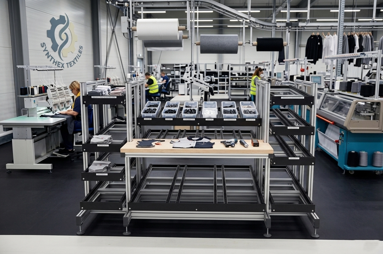
Key Features

Multi-Side Cell Supply

Rack segments engineered to U-cell, C-cell, and island perimeters — components accessible from all operator positions within the cell without crossing boundaries.

Corner Connector Structures

T-slot corner frames join rack segments at cell corners without gaps — continuous component supply around the full cell perimeter.

Cell Geometry Engineering

Rack depth and lane layout engineered to the specific cell geometry — no wasted reach distance at any operator position in the cell.

Inner Cell Staging

Inner cell surface provides kit tote staging, sub-assembly staging, and WIP buffer positions within the operator's immediate reach.

Replenishment from Outer Perimeter

All lanes loaded from the outer cell perimeter by the replenishment operator — no entry into the operator cell during replenishment.

Flexible Cell Footprint

T-slot frames configure to any cell shape and size — square, rectangular, or irregular footprints served by the same modular hardware.

Specifications

Cell Configurations U-cell, C-cell, island, linear
Lane Width Range 50 mm – 400 mm adjustable
Lane Depth 200 mm – 600 mm
Rack Height Up to 1800 mm
Number of Tiers 2 – 4
Track Type Plastic wheel
Corner Frame Type 45° or 90° T-slot connectors
Frame Material 6063-T5 aluminum extrusion
Max Component Weight 15 kg per lane
Cell Entry Width 600 mm – 1200 mm
Replenishment Access Outer perimeter rear-load
Frame Finish Clear anodized or powder coat

Applications & Use Cases

Lean U-Cell Assembly

Classic Toyota-style U-cell with all component lanes on the inner perimeter — operators complete full assembly cycles within the cell without leaving.

Mixed-Model Assembly Cells

C-cell and island configurations for high-mix low-volume production — rapid lane reconfiguration between model variants within the same cell structure.

Electronics Assembly Cells

Compact U-cell flow racks for PCB and electronic assembly — all components within 400mm reach at every operator position in the cell.

Medical Device Assembly Cells

ISO 13485 work cells with controlled component flow — FIFO rotation and lane-level lot tracking within a compact cell perimeter.

Final Assembly Islands

Island cell configurations for large assembly operations — components supplied from all four sides of a central assembly fixture.

Inspection and Test Cells

C-cell configurations for combined assembly, inspection, and test operations — all materials and equipment within operator reach in a single cell.

Welding and Fabrication Cells

U-cell flow racks surrounding welding fixtures — hardware, consumables, and fixtures at reach from any position within the welding cell.

Training and Simulation Cells

Modular T-slot cell structures for lean training and simulation — rapid layout reconfiguration between training scenarios.

Frequently Asked Questions

What is the minimum cell size that can be served by work cell flow racks?

Minimum practical cell inner dimension is approximately 1200mm x 1200mm for a U-cell or island configuration, allowing a single operator to work within the cell and access all perimeter lanes. Smaller cells below this size restrict operator movement between stations.

How are rack segments joined at cell corners?

T-slot 45° and 90° corner connectors join adjacent rack segments at cell corners with standard M8 T-bolts. Corner joints are flush and gap-free — no exposed frame ends or trip hazards at cell corners.

Can the cell be expanded after installation?

Yes. Cell perimeter segments are independent structures joined at corners — additional segments extend the cell perimeter. Corner connectors accept third-direction segments to transition from a U-cell to a C-cell or island configuration with minimal hardware changes.

How is replenishment performed without entering the operator cell?

All lanes load from the outer perimeter. Replenishment operators work the outer face of the cell perimeter — they never enter the operator cell during replenishment. This is a fundamental safety and flow design requirement for work cell configurations.

What is the standard lane depth for work cell racks?

Standard cell rack depths are 200–400mm — sufficient to hold one replenishment cycle while keeping the cell perimeter footprint compact. Deeper lanes are used for high-velocity components where replenishment frequency must be minimised.

Can work cell racks integrate with automated guided vehicles for replenishment?

Yes. Outer perimeter lane face heights are designed to standard AGV delivery height. AGV-compatible configurations include standardised lane opening dimensions matched to AGV gripper specifications for automated outer-perimeter replenishment without manual handling.

Ready to Get Started?

Request a quote or contact our engineering team to discuss your work cell flow racks requirements.

Request a Quote Contact Engineering