Restricted-access robotic enclosures for the highest-risk applications — featuring Category 3/PLd safety-rated interlock switches, dual-channel E-stop integration, safety PLC compatibility, light curtain and area scanner provisions, and trapped-key interlock systems. Engineered to meet ISO 10218 and ISO 13849 requirements for regulated, aerospace, medical, and automotive industries.
Request a Quote
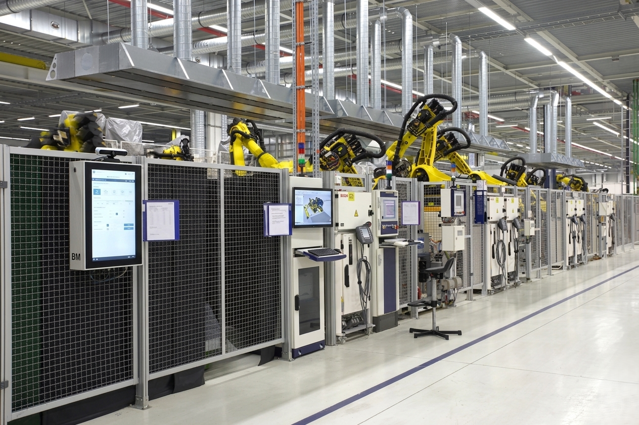
When regulatory compliance and maximum personnel protection are non-negotiable, our electronic guarding systems provide the documented safety performance your facility requires.
Interlock switches and safety circuits specified and wired to achieve Category 3, Performance Level d (PLd) per ISO 13849 — documented with safety calculations.
Interlock switch and E-stop wiring terminated to safety relay or safety PLC I/O — compatible with Siemens, Allen-Bradley, Pilz, Sick, and Omron safety controllers.
Trapped-key (Castell, Kirk, or Fortress) interlock systems prevent access to the robot cell until the power-down sequence is completed and the key is released.
Safety light curtain mounting brackets and wiring provisions for SICK, Keyence, Banner, and Omron Type 4 safety light curtains at personnel access points.
Guarding layouts designed in accordance with ISO 10218-1 and ISO 10218-2 for industrial robot safety — minimum safety distances, gap limits, and opening sizes all verified.
Full documentation package available: safety distance calculations, risk assessment summary, wiring schematics, and safety function performance level verification.
High-security robotic enclosures from Modular Solutions go beyond structural containment to deliver verified electronic safety performance at every access point.
All safety-rated interlock switches wired in dual-channel (two-wire) configuration — providing fault detection and preventing single-point failures from bypassing the safety function.
Controlled access openings with safety light curtain muting or blanking configured for product flow while maintaining safety integrity during part transfer operations.
Multiple padlock positions on all gate mechanisms for lockout/tagout compliance per OSHA 29 CFR 1910.147 — maintenance access with full energy isolation confirmation.
High-coded RFID safety switches (Schmersal, Pilz, Sick) on critical access points — tamper-resistant, unique coding prevents defeat with foreign objects.
Guard monitoring circuits prevent automatic restart of robot motion after safety function activation — operator must perform deliberate reset action before production resumes.
Stack light or panel-mount indicator provisions show cell state (running, faulted, safe entry) — integrated with the safety circuit output for accurate status indication.
High-security e-guarding is specified for the most regulated and highest-consequence robotic applications.
Representative system parameters — all specifications are custom-engineered to your safety performance level requirements.
Category 3 / Performance Level d (PLd) per ISO 13849-1 defines a safety function that tolerates a single fault without loss of the safety function — achieved through dual-channel wiring, safety-rated components, and fault detection. For robot guarding, this means the safety interlock circuit is wired so that a single wire break or component failure does not result in the safety gate being able to be opened without stopping the robot.
A trapped-key interlock system requires that a specific sequence of actions — typically robot power-down and confirmation — must be completed before the key is released from a lock, and that key must be inserted into the gate lock before the gate can be opened. The key is physically 'trapped' in the first lock until the robot is safe, preventing access while the robot is energized. Modular Solutions uses Castell, Kirk, and Fortress trapped-key systems.
ISO 13849-1 provides the framework for designing and verifying safety-related control functions — including the gate interlock circuits on robotic guarding. It defines performance levels (PLa–PLe) and categories (B, 1, 2, 3, 4) that specify how safety functions must be structured and how their reliability must be calculated. Most robot cell guard interlocks are designed to at least Category 3, PLd.
Yes. Modular Solutions terminates all safety interlock and E-stop wiring to a terminal strip for connection to the customer's existing safety PLC (Siemens, Allen-Bradley, Pilz, Omron) or safety relay. Wiring schematics are provided showing the connection points for each safety function so the facility electrical team can integrate the guard into the existing safety architecture.
The standard documentation package includes: mechanical CAD drawings and BOM, safety interlock wiring schematics, safety distance calculation sheets (per ANSI/RIA R15.06 and ISO 13857), ISO 13849-1 performance level verification summary, and a risk reduction summary documenting how each identified hazard was addressed by the guard design.
Contact our engineering team for a high-security robotic enclosure with full safety performance documentation — ISO 13849 calculations, wiring schematics, and risk assessment summary included.
Request a Custom Quote