Equipment Mounting Tables
Modular aluminum equipment mounting tables engineered for production equipment, automation controllers, test systems, and instrumentation racks. Integrated cable management, utility routing, precision leveling, and equipment anchor provisions — all in a single T-slot structure that adapts when equipment changes.
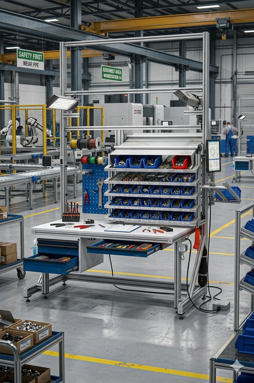
Why Choose Equipment Mounting Tables?
Equipment mounting tables are more than a base. They manage cables, route utilities, provide access for maintenance, and position equipment precisely. Modular T-slot construction handles all of these simultaneously.
Modular aluminum T-slot structural tables bolt together without welding and reconfigure without tools — delivering the rigidity and load capacity of a dedicated machine base with the flexibility to adapt through every process change, equipment upgrade, and facility reorganization without replacing the structure.
Integrated Cable Management
In-frame cable channels route power, signal, and communication cables from the source to the equipment without exposed conduit or surface raceways.
Utility Routing Provisions
Compressed air, coolant, and pneumatic provisions route through dedicated frame channels with quick-connect fittings at the equipment mount points.
Precision Leveling
Adjustable leveling pads with sub-millimeter adjustment range position equipment within the alignment tolerance required by the process.
Equipment Anchor Provisions
Pre-drilled anchor patterns accept equipment mounting bolts directly — matching common equipment footprint layouts without fabrication.
Maintenance Access Panels
Removable side and end panels provide front and side access to cables, utilities, and equipment undercarriage for maintenance.
Electrical Panel Integration
Provisions for control panel mounting, DIN rail installation, and terminal block strips inside the table structure.
Applications
Equipment mounting tables are deployed for a wide range of production, test, and automation system installations.
- CNC control cabinet bases
- Automation PLC and HMI stations
- Test bench instrument rack bases
- Vision system and camera mount tables
- Conveyor drive and motor bases
- Welding power supply and controller bases
- Laser system controller and chiller bases
- Hydraulic power unit staging tables
Specifications
Standard specifications for modular aluminum equipment mounting table configurations.
| Parameter | Detail |
|---|---|
| Frame Profile | 90mm T-slot aluminum extrusion; 45mm for lighter equipment |
| Surface Material | Aluminum plate or steel plate; open-frame base option for utility routing |
| Cable Management | In-frame channels, surface grommets, and rear cable exit provisions |
| Utility Routing | Air, coolant, and electrical provisions; quick-connect fittings at mounting points |
| Leveling | M20–M30 pads; 1/2" adjustment range; jam-nut lock |
| Equipment Anchors | Through-bolt patterns to equipment footprint spec; custom patterns available |
| Standard Sizes | 24"×36" to 72"×120" — custom footprints to equipment spec |
| Lead Time | 4–6 weeks from approved drawings |
Frequently Asked Questions
Common questions about equipment mounting table cable management, utility routing, and anchor provisions.
How is cable management integrated into an equipment mounting table?
Cable channels are machined into the hollow T-slot frame extrusion sections and run vertically through leg uprights and horizontally through base cross-members. Cables enter the frame through a designated entry point, route internally to the equipment mounting area, and exit through surface-level grommets at each equipment connection point. All cable channels are accessible by loosening T-bolt cover panels — no conduit removal required for cable changes.
What utility connections can be integrated into an equipment mounting table?
Compressed air provisions include a main supply inlet, internal distribution manifold in the frame, and quick-connect fittings at each equipment mount point. Coolant routing uses sealed tubing in dedicated frame channels with shut-off valves at each equipment connection. Electrical provisions include conduit routing, junction boxes, and terminal block strips. All utility provisions are specified during the design phase based on the equipment utility requirements.
Can equipment mounting tables be shared between multiple pieces of equipment?
Yes. T-slot surface and frame construction allows multiple pieces of equipment to be mounted on a single table in a defined spatial arrangement. Each equipment position has its own anchor provisions, cable exit points, and utility connections. When equipment is relocated or replaced, unused provisions are capped and new provisions are added by drilling into the frame at the required position.
How are control panels and electrical enclosures integrated?
Control panels and enclosures mount to T-slot uprights or the table surface via T-bolt fasteners — no drilling required. DIN rail strips, terminal block brackets, and cable management saddles attach directly to the frame T-slot channels inside the enclosure provisions. This allows the control panel to be integrated into the table structure rather than as a separate free-standing cabinet, reducing floor footprint.
What is the lead time for custom equipment mounting tables?
Standard equipment mounting table configurations ship in 4 to 6 weeks from approved drawings. Configurations with complex utility routing, custom anchor patterns, integrated electrical provisions, or cleanroom-compatible construction require 5 to 8 weeks. Lead time is confirmed after engineering review of the equipment utility and mounting specifications.
Ready to Configure Your Equipment Mounting Tables?
Contact our structural engineering team for a no-obligation quote. We design, engineer, and manufacture heavy duty modular tables from our Auburn Hills, MI facility — typically shipping in 3–6 weeks from approved drawings.
Request a Quote