Heavy-gauge gravity flow lanes for engine blocks, cylinder heads, crankshafts, transmission cases, and complete powertrain assemblies in carriers — engineered to protect machined surfaces and deliver components to assembly stations in precise FIFO sequence. Manufactured in Auburn Hills, MI.
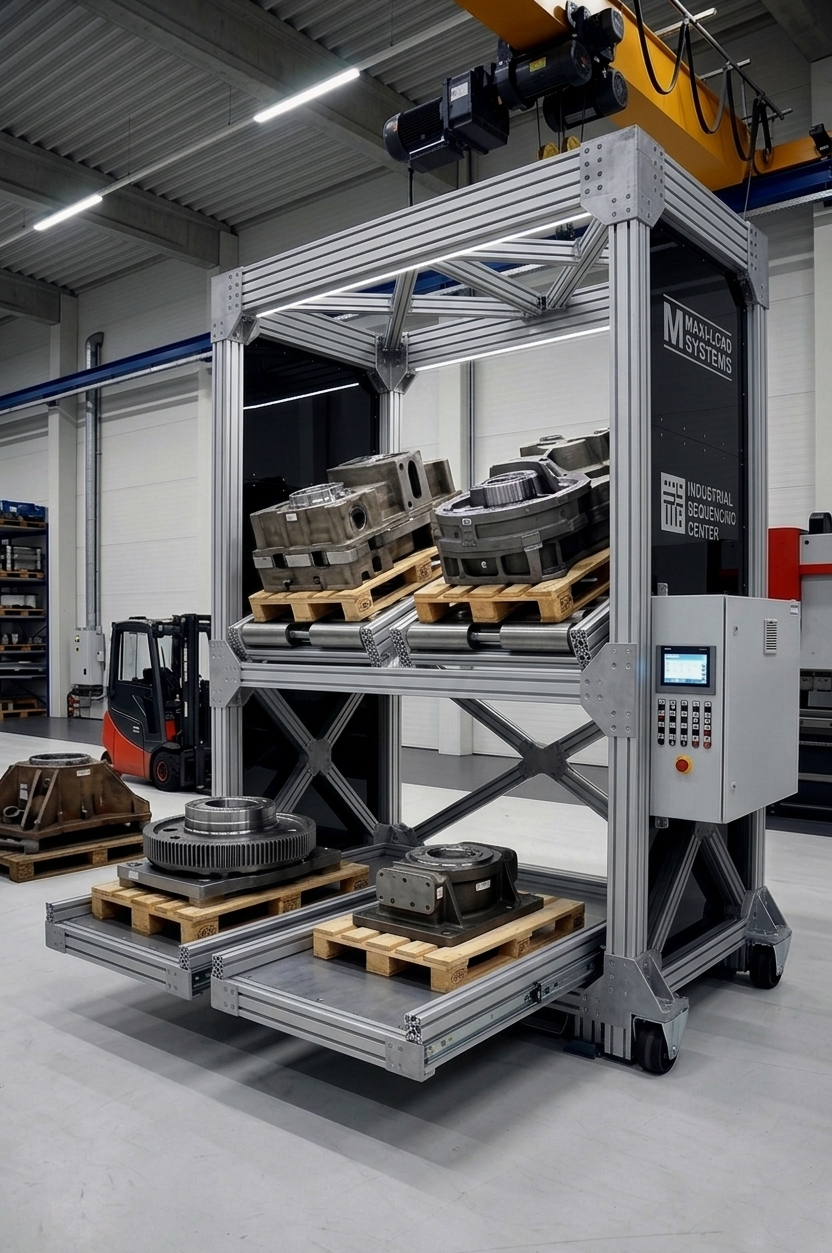
Lanes are designed around the specific engine carrier or dunnage tray in use — matching roller pitch and guide geometry to the carrier base for consistent support and alignment throughout the full lane depth.
Speed controllers and rubber end stops limit pick-face impact velocity — preventing damage to precision machined bores, gasket faces, and threaded ports from carrier-to-stop contact.
Multi-lane configurations present multiple engine families or build variants side-by-side, with lane-by-variant assignment matching the assembly station's build sequence requirements.
Stainless rollers, galvanized rail, and sealed bearings are available for lanes adjacent to wash stations, hot test cells, and high-humidity powertrain assembly environments.
Pick-face height and roller centerline are designed to match the receiving assembly conveyor or transfer lift datum — enabling direct carrier transfer without manual repositioning.
Lane-empty presence sensors signal WMS or plant andon systems when an engine family lane requires replenishment — eliminating production line-stops from late carrier delivery.
Custom to carrier footprint; typical 24–48 in. for engine carrier widths; larger for complete assembly carriers
250 lbs to 2,000+ lbs per carrier position; rated to gross carrier + component weight with 2:1 safety factor
60–90mm per load rating; rubber-coated rollers available for carrier surface protection
3–4% standard; adjusted per carrier base friction and load weight; speed controllers per lane
2-deep to 5-deep; depth matched to production line buffer and replenishment cycle requirements
Rubber-cushioned positive stop at pick face; stop force calculated from carrier velocity and mass
Floor-level or elevated to match assembly conveyor; custom heights for ergonomic operator access
Powder coat standard; stainless roller track and galvanized frame for wash-down environments
Photoelectric lane-empty sensors at pick face; output to plant WMS, MES, or andon board
FIFO carrier lanes presenting machined engine blocks to assembly line transfer conveyors.
Gravity flow lanes for cylinder head carriers delivering heads to valve train assembly stations.
Transmission case carrier staging for planetary and torque converter assembly line supply.
Crankshaft carrier lanes feeding crankshaft balancing and installation stations in FIFO order.
Complete long-block assembly carrier staging for final engine assembly and hot-test sequencing.
Used engine core staging lanes in remanufacturing facilities for FIFO teardown sequencing.
Large diesel and stationary engine component staging in heavy-load carrier flow lanes.
Marine block and drive component carrier staging for outboard and inboard engine assembly lines.
Yes, provided the flow rack design accounts for the part weight, center of gravity, and machined surface protection. Engine blocks typically arrive in dedicated carriers or dunnage trays. The flow lane is designed for the carrier, not the bare block. Roller pitch, speed controller settings, and end-stop force are all calculated to prevent impact damage to machined bores and gasket surfaces at the pick face.
A typical V8 engine block in a steel carrier weighs 400–600 lbs per position. Complete long-block assemblies with accessories can reach 800–1,200 lbs. Inline-4 and 6-cylinder units in carriers typically run 250–500 lbs. Lane rating is calculated from the specific engine family and carrier weight, with a 2:1 minimum safety factor applied to the rated position load.
Engine components are flowed in their production dunnage or dedicated steel carriers that protect all machined surfaces. The flow rack lane is designed for the carrier footprint, and roller pitch is set so the carrier is always supported by at least three rollers. Speed controllers limit pick-face impact velocity to prevent dunnage damage. Rubber bumpers on end stops provide a soft positive stop.
Yes. Flow racks adjacent to hot-test cells or wash stations require corrosion-resistant hardware. We specify stainless steel roller tracks, galvanized steel rail, sealed bearings, and epoxy or powder coat primers for high-humidity and wash-down zones. Drain channels can be integrated in the lane structure to manage water runoff from washed components.
Engine component flow rack pick faces are designed to match the height and datum position of the receiving assembly line conveyor or transfer lift. The carrier slides or rolls directly from the flow lane onto the conveyor without manual repositioning. Carrier guide rails on the conveyor entry align the transfer, eliminating the need for operator correction of carrier orientation.
Provide your carrier drawings, engine family weights, lane count, and assembly conveyor interface heights — our engineers will design a system matched to your powertrain operation.
Request a Quote