Production Buffer Flow Racks

Inter-operation WIP buffer flow racks sized to defined container quantities — physically decoupling upstream and downstream cycle times, enforcing WIP caps, and pacing production without electronic control systems or operator judgment.
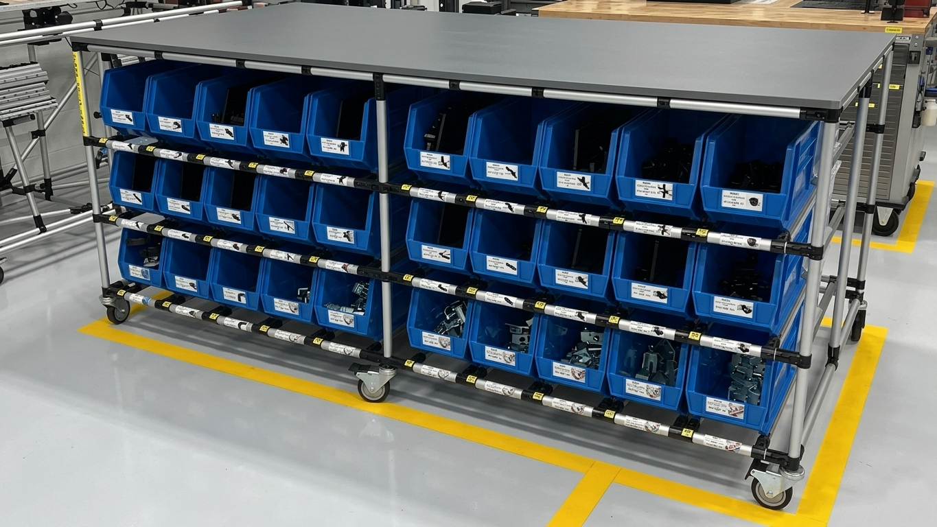
Why Choose Production Buffer Flow Racks

A production buffer rack is a production system tool — it decouples two operations, enforces the WIP cap, sequences FIFO, and paces the upstream process, all through rack geometry alone.

Cycle Time Decoupling

Lane depth is sized to absorb the cycle time variation between the upstream and downstream operation. Minor stoppages and speed fluctuations at either station do not immediately starve or block the adjacent operation.

WIP Cap Enforcement

The physical lane depth defines the maximum WIP between the two operations. When the lane is full, there is no space for the upstream process to deposit another container — the buffer is the stop signal for overproduction.

FIFO Inter-Operation Sequencing

Rear-load, front-pick lane geometry ensures that the downstream operation always processes containers in the order they were produced upstream. Production sequence is maintained through the buffer without operator intervention or system tracking.

Production Pacing Without Electronics

Full lane = stop upstream. Empty lane = upstream runs. The rack physically communicates the production pace between operations using container presence alone — no PLC, no sensor, no visual management required for the basic pacing function.

Lane-Full Sensor Option

For automated upstream operations that cannot be stopped manually, a lane-full sensor mounts at the lane rear opening and triggers an automatic stop signal to the upstream machine or conveyor system when the buffer lane reaches capacity.

Compact Inter-Operation Footprint

Buffer racks are designed to the minimum footprint that holds the required buffer quantity — single-tier, single-lane configurations are standard for inline inter-operation buffers where floor space between the two stations is limited.

Specifications

Frame Profile

45mm or 90mm aluminum T-slot extrusion

Buffer Sizing

Lane depth calculated from cycle time variation data

Lane Configuration

Single-lane to multi-lane; single-tier to 5-tier

Lane Track Types

Roller track, skate wheel, or poly-wheel rail

Lane Pitch

2%–8% adjustable; set to container weight

Load Capacity

Up to 500kg per lane; up to 1000kg per bay

Lane-Full Sensor

Photoelectric sensor at rear lane opening; optional

Footprint

Designed to minimum inter-operation floor space

Finish

Natural anodized aluminum; color-coded container labels

Applications

Production buffer flow racks are used wherever two adjacent operations have different cycle times, maintenance frequencies, or throughput rates that would cause starving or blocking without a buffer.

Machine-to-Assembly Buffer

Buffer between a machining center and the downstream assembly station absorbs cycle time variation from tool changes, setup, and inspection without stopping the assembly line.

Sub-Assembly Staging

Sub-assembly buffer racks hold completed sub-assemblies in FIFO sequence before delivery to the main assembly line, decoupling sub-assembly production from main line takt.

Inspection Queue Buffer

Buffer between a production operation and an inspection station holds parts waiting for inspection without blocking the producing operation or creating an uncontrolled WIP pile.

Batch Process Decoupling

Between a batch process (oven, wash, cure) and a single-piece downstream operation, a buffer rack holds the batch output in FIFO sequence and feeds the downstream process at takt rate.

Frequently Asked Questions

What is the purpose of a production buffer flow rack?

A production buffer flow rack is positioned between two adjacent operations in the production process. Its purpose is to decouple the cycle times of the upstream and downstream operations so that a minor stoppage or speed variation at one operation does not immediately starve or block the other. The buffer lane depth is calculated to provide enough WIP to cover the maximum expected variation in cycle time between the two operations.

How is buffer rack lane depth calculated?

Buffer lane depth is calculated from the cycle time difference between the upstream and downstream operations plus a safety margin. The formula is: buffer quantity = (cycle time variation in seconds / downstream takt time) + safety stock containers. Modular Solutions performs this calculation with the customer's production data and documents the resulting buffer size in the rack design specification.

Can a production buffer rack serve as both a FIFO buffer and a WIP cap?

Yes. The rear-load, front-pick lane geometry enforces FIFO sequence in the buffer. The lane depth physically limits the maximum WIP between the two operations — the upstream operation cannot produce more than the lane holds. When the lane is full, the upstream process must stop or slow, which is the intended production pacing signal.

How does a full buffer lane signal the upstream operation to stop?

When the buffer lane is full, the upstream operator has no place to put the completed container — the rack is the stop signal. For automated upstream operations, a lane-full sensor can trigger an automatic stop signal to the upstream machine.

Can production buffer racks be used in a one-piece flow cell?

In a true one-piece flow cell, inter-operation buffers are eliminated and containers flow directly from one station to the next. A production buffer rack would only be introduced between two operations in a one-piece flow cell if the cycle time variation between them is too large to absorb at the workstation level.

Design Your Production Buffer Rack

Share your upstream and downstream cycle times, container sizes, and inter-operation floor space — we will calculate the buffer size and design the rack to fit your production layout.

Request a Quote