Vision Inspection Stations
Modular aluminum stations purpose-built for machine vision quality inspection — with precision camera mounting structures, controlled lighting frames, ambient light baffles, part fixture provisions, and accept/reject routing integrated into the aluminum T-slot structure. Designed around your camera system, lens, and lighting configuration. Designed and manufactured in Auburn Hills, MI.
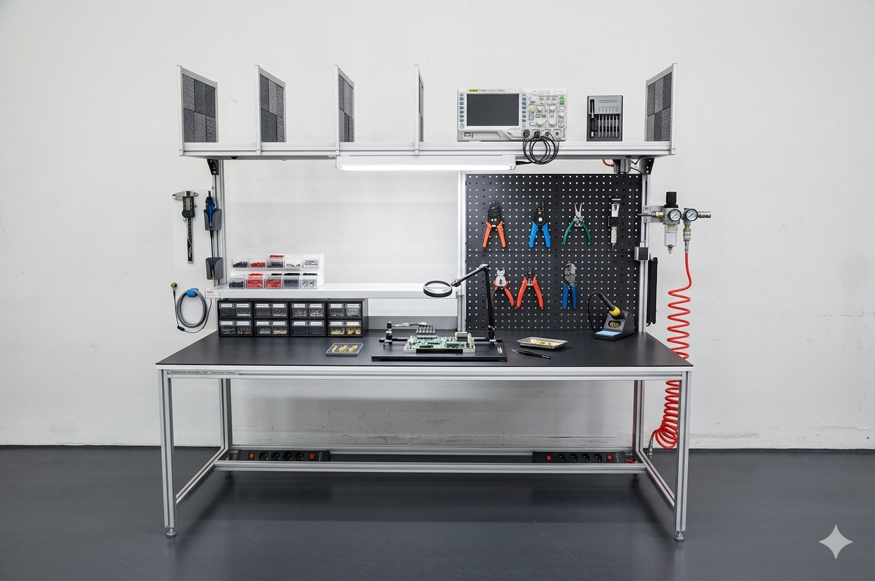
Why Choose Modular Solutions for Vision Inspection Stations?
Engineered for repeatable image capture — rigid camera positions, controlled lighting, and no ambient light interference.
Modular aluminum T-slot workstations bolt together without welding and reconfigure without tools — giving you a purpose-engineered station today that adapts through every process change, product launch, and kaizen event without capital reinvestment in new furniture.
Precision Camera Mounts
Camera mounting plates on 45mm T-slot uprights or overhead crossbars position cameras at calibrated working distances with 1/4-20 and M6 thread patterns — adjustable without drilling during commissioning.
Controlled Lighting Structures
Overhead lighting frames position ring lights, backlights, and structured light sources at calibrated distances and angles for consistent illumination across every inspection cycle.
Ambient Light Baffles
Three-sided blackout curtain or rigid panel enclosures on the T-slot frame eliminate ambient light variation that causes false rejects in machine vision algorithms.
Part Fixture Provisions
Custom fixture mounting plates locate parts at a repeatable position and orientation within the camera field of view — with manual or pneumatic clamp options for fast part loading.
Accept/Reject Routing
Indicator lights, audible alerts, and divert gate provisions route accepted and rejected parts to separate output lanes or bins based on vision controller pass/fail output signals.
Vision Controller Integration
Controller, PC, and monitor mount positions built into the T-slot upright structure — with cable management channels routing vision system, lighting, and I/O wiring cleanly through the frame.
Vision Inspection Station Applications
Configured for machine vision quality inspection across manufacturing and production environments.
- Dimensional Gauging Stations — Inline or off-line dimensional measurement stations using 2D vision or 3D laser profilers to verify part dimensions against CAD tolerances before assembly or shipment.
- Surface Defect Detection — Bright-field and dark-field inspection stations for surface scratch, crack, porosity, and cosmetic defect detection on machined, cast, or molded parts.
- Presence & Completeness Checks — Assembly verification stations confirming correct component presence, orientation, color, and label placement before boxing or downstream process.
- Barcode & OCR Verification — Label and barcode reading stations with controlled backlighting for reliable 1D/2D code reading and OCR character verification at production line speeds.
- PCB & Electronics AOI — Automated optical inspection support stations for PCB soldering quality, component placement, and marking verification outside of dedicated AOI machine envelopes.
- Medical Device Inspection — Validated inspection stations with documented lighting repeatability and fixture qualification for FDA-regulated medical device visual inspection processes.
Specifications & Configurations
Standard configurations available — all camera mount positions and lighting layouts are custom-engineered to your vision system requirements.
| Specification | Detail |
|---|---|
| Frame Profile | 45mm T-slot aluminum; rigid overhead camera bar on 90mm uprights for heavy camera/lens combinations |
| Camera Mount Thread | 1/4-20 and M6 standard; M8 available; custom mounting plates for specialty camera bodies |
| Lighting Mount Height | Adjustable from 12” to 48” above inspection surface; calibrated spacers available |
| Enclosure Options | Blackout curtain (3-side, floor-length), rigid opaque panel enclosure, or open-access for inline integration |
| Vibration Isolation | Anti-vibration leveling feet standard; active isolation mounts available for sub-mm resolution applications |
| Controller Mount | Side upright or overhead panel mount for vision controller, PC, and monitor; cable management integrated |
| Lead Time | 3–5 weeks from approved drawings and camera system dimensions |
Frequently Asked Questions
Common questions about vision inspection station design and machine vision integration.
How are cameras mounted on vision inspection stations?
Camera mounts attach to 45mm T-slot extrusion uprights or overhead crossbars using precision camera mounting plates with 1/4-20 and M6 thread patterns. Mounting positions are set during the vision system layout phase to achieve the correct field of view and working distance. Positions can be adjusted along the T-slot without drilling when the vision system is commissioned or reconfigured for different part sizes.
How is lighting controlled at a vision inspection station?
Lighting structures mount to the overhead T-slot frame at calibrated distances above the inspection surface. Dark-field, bright-field, backlighting, and coaxial lighting configurations are supported. Light baffles and blackout curtains on three sides of the station prevent ambient light interference with the machine vision algorithm. Strobe controllers and LED driver mounts integrate into the upright structure.
Is vibration isolation required for vision inspection stations?
Vibration isolation depends on the inspection resolution and production floor vibration profile. For high-resolution inspection of small features (sub-millimeter tolerances), isolation pads or active isolation mounts under the station legs reduce floor vibration transmission. For lower-resolution inspection or off-line stations away from heavy equipment, standard leveling feet are typically sufficient.
Can part fixtures be integrated into the vision station structure?
Yes. Part fixture mounting provisions are machined into the work surface or attached to the T-slot surface using custom fixture plates. Fixtures locate parts at a repeatable position and orientation within the camera field of view for consistent inspection results. Fixture change mechanisms (manual or pneumatic clamp) can also be integrated into the station structure.
How are accept/reject decisions handled at the station?
Accept/reject signal outputs from the vision controller connect to indicator lights, audible alerts, and divert gates that route accepted and rejected parts to separate output lanes or bins. Signal wiring is routed through the T-slot frame structure to a junction box. For integrated line systems, the vision station controller interfaces with the upstream PLC or MES over Ethernet or discrete I/O.
Build Your Vision Inspection Station
Share your camera system, lens working distance, lighting configuration, and part dimensions — our engineers will return a station drawing configured to your vision system layout.