Automation-Integrated Cart Systems
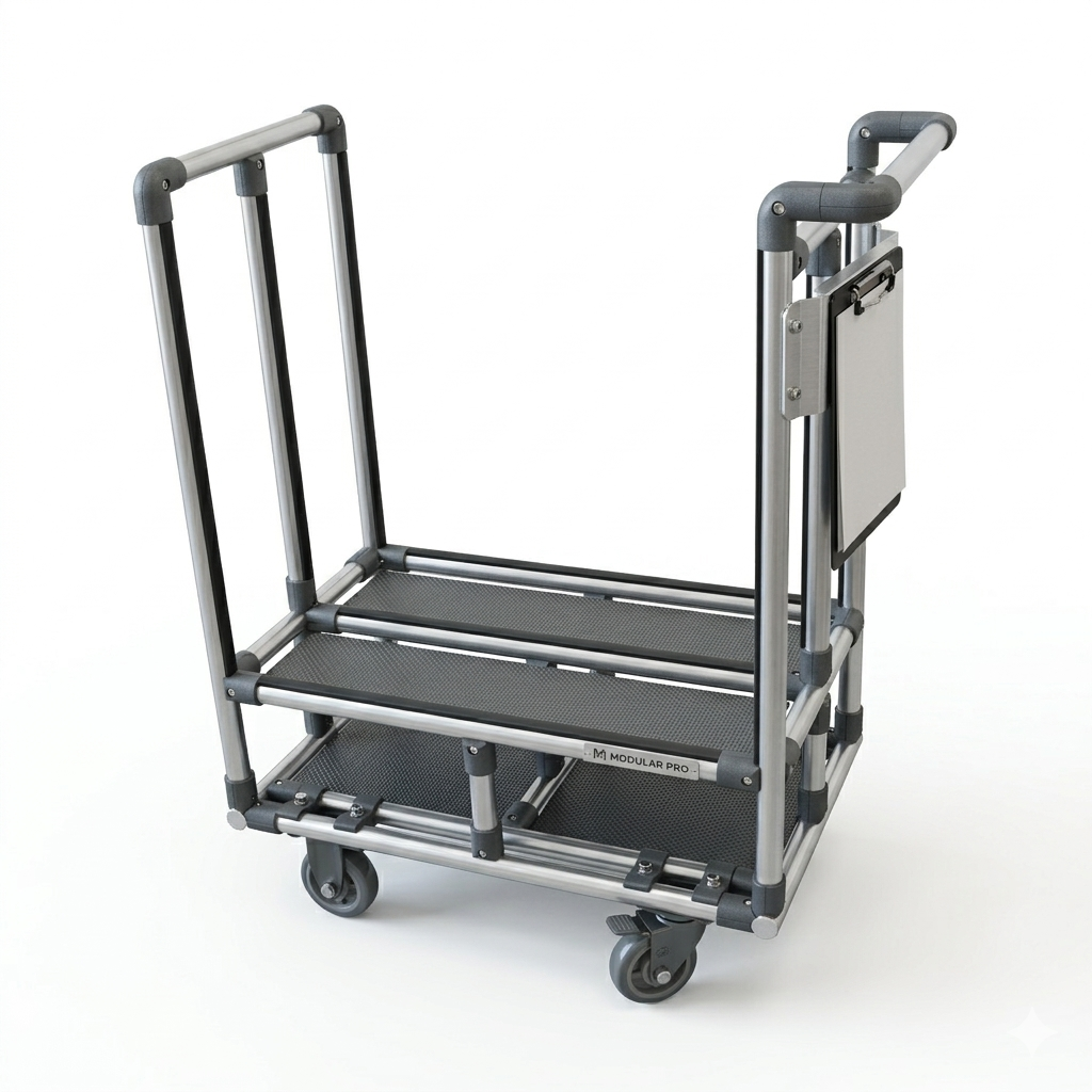
T-slot aluminum cart systems designed as mechanical components of automated production cells — engineered alongside robots, conveyors, vision systems, and fixtures to satisfy robot reach envelope clearance, vision system field of view, fixture interface geometry, and teach pendant access requirements. The cart is part of the cell, not equipment that the cell has to work around.
Why Design Carts as Part of the Automation Cell?
A standard cart positioned next to an automation cell is not the same as a cart designed as part of that cell. The difference shows up in robot reach utilization, vision system reliability, and commissioning time.
Designed in the Cell Layout, Not Around It
Cart height, deck position, and footprint are established during cell layout — alongside the robot mounting, fixture position, and conveyor envelope. The cart is dimensioned to place the part pickup surface within the robot's optimal reach zone, not at whatever height a standard cart happens to be. Robot path efficiency and joint limit margin are designed in from the start.
Robot Reach Envelope Clearance
The cart frame geometry is verified against the robot's full path envelope — not just the nominal pickup path — to confirm that the cart structure does not enter the robot's working space during any part of the programmed cycle. Frame clearance is confirmed in the cell CAD model before fabrication, eliminating interference discoveries at commissioning.
Vision System Field-of-View Clearance
For cells using 2D or 3D vision systems for part location on the cart, the cart deck geometry, deck surface reflectivity, and frame shadow pattern are designed to produce consistent, low-noise images in the vision system's field of view. Camera mount provisions and lighting bracket positions can be incorporated into the T-slot cart frame structure.
Fixture Interface Geometry
When the cart delivers parts directly into a fixture or nest at the automation cell, the cart deck geometry is designed with the positional tolerance needed for reliable fixture engagement — including cell dock locating features, deck height alignment, and part presentation angle. Fixture interface provisions are dimensioned on the cart drawing to allow cross-checking with the fixture design before fabrication.
Teach Pendant and Maintenance Access
Cell layouts must preserve robot teach pendant access and maintenance clearance to the robot and cell equipment. Cart geometry is reviewed against the teach position and service access envelopes to confirm that the cart in its docked position does not block access required for routine operation, programming, and maintenance.
Cell Dock Positioning Provisions
Mechanical stop features, guide pins, and cart presence sensors at the cell dock position the cart within the robot's programmed pickup coordinate tolerance — without requiring the robot program to accommodate variable cart position. Consistent cart docking eliminates pickup miss errors caused by cart position variation in high-cycle automated operation.
Key Features & Benefits
Integration details that make automation-compatible T-slot cart systems reliable in continuous robotic production operation.
Part Nests and Pickup Datum Features
Part nests, cradles, and locating pins on the cart deck position parts at the robot's programmed pickup coordinates with the repeatability required for reliable automated pick. Nest geometry is designed from the part model and the robot's TCP definition — confirmed against the robot reach model before the cart drawing is released.
Cell Safety Boundary Compatibility
Cart geometry is reviewed against the cell safety fence layout to confirm that the cart in its operational position does not interfere with the safety boundary or sensor zones. Cart presence detection at the cell dock is incorporated into the cell safety logic design to ensure that robot operation is interlocked with verified cart position.
Deck Surface for Vision Consistency
Deck surface material, texture, and color are selected for consistent contrast against the parts being handled — supporting reliable part detection and localization by the cell vision system. Anti-glare surfaces, contrasting deck inserts, and structured background patterns are available as deck surface options.
Cart Presence and Position Detection
Proximity sensors or RFID readers at the cell dock confirm that the cart is present, correctly positioned, and the correct cart variant for the current production recipe before the robot cycle is enabled. Detection provisions are integrated into the cart frame and wired to the cell control panel through the dock junction box.
Multiple Cart Positions per Cell
Automation cells with infeed and outfeed carts, or multiple part type positions, use T-slot carts at each position — all designed to the same cell layout model with consistent dock provisions. Multiple cart positions in the same cell are designed simultaneously to prevent conflicts between cart frames, robot paths, and conveyor interfaces.
T-Slot Adjustability for Cell Commissioning
T-slot cart frames retain adjustability during cell commissioning — part nest positions, deck accessories, and sensor mounts can be repositioned within the T-slot channels to fine-tune part presentation before the robot program is finalized. This adjustability shortens commissioning time significantly compared to welded steel carts, where commissioning changes require fabrication rework.
Common Applications
Used in automation cells where the cart is a functional part of the cell layout — not peripheral equipment that the automation system must accommodate.
- Robotic Part Loading Cells - Carts positioned at the robot infeed position of a CNC machining cell or press, presenting raw parts at the robot's programmed pickup position and returning loaded carts of finished parts at the outfeed position.
- Vision-Guided Robotic Pick Cells - Carts delivering bulk or semi-random parts to the robot's vision system field of view for bin-picking or structured pick applications, with deck geometry and surface design optimized for the vision system's part detection algorithm.
- Assembly Cell Infeed and Outfeed - Infeed carts presenting components to the robot at the assembly cell pickup station, and outfeed carts receiving completed assemblies from the robot at the cell deposit position — all sized and positioned within the cell layout model before fabrication.
- Collaborative Robot (Cobot) Work Cells - Carts designed for collaborative robot work cells with ergonomic access for human operators sharing the cart space alongside the cobot, deck geometry matched to the cobot's reach limits, and safety-compliant profile edge treatments at the shared human-robot zone boundary.
- End-of-Line Automated Inspection Cells - Carts delivering finished goods to the inspection cell camera or laser scanner field of view at the correct height and orientation for consistent automated inspection image capture without manual part repositioning.
- Automated Dispensing and Application Cells - Carts presenting assemblies or sub-assemblies to automated adhesive dispensing, welding, or coating cells at the process nozzle or electrode height — with datum features positioning the part surface at the process tool's working distance.
Specifications & Configurations
Design parameters for automation-integrated cart systems. All dimensions are established during cell layout before fabrication.
| Specification | Detail |
|---|---|
| Frame Profile | 45 or 90 Series T-slot aluminum; hybrid steel insert available for load/precision requirements |
| Part Positioning | Nests, cradles, locating pins, datum blocks; toleranced to robot TCP pickup requirement |
| Dock Interface | Mechanical stops, guide pins, cart presence detection; standard I/O to cell PLC |
| Vision Compatibility | Deck surface options for 2D/3D vision contrast; camera and lighting mount provisions |
| Robot Clearance | Frame envelope verified against robot path model before fabrication release |
| Safety Provisions | Edge bumpers, reflective marking, safety interlocks per cell safety specification |
| Adjustability | T-slot channels retained for commissioning adjustment of nests, sensors, accessories |
| Lead Time | 5 to 9 weeks from approved design; coordinated with cell layout schedule |
Frequently Asked Questions
Common questions about automation-integrated cart systems from Modular Solutions.
How is a cart designed as part of an automation cell rather than as a separate piece of equipment?
A cart designed as part of an automation cell is dimensioned and positioned in the cell layout model alongside the robot, fixtures, and conveyors before any hardware is fabricated. The cart height, deck geometry, and position are set to satisfy the robot's reach envelope, TCP offset, and joint angle limits at the part pickup position. Clearance between the cart frame and the robot's maximum path envelope is confirmed in the cell model. The result is a cart that fits the automation cell precisely — rather than a standard cart that the robot program tries to work around.
What information does Modular Solutions need to design a cart for a robotic cell?
To design a cart for a robotic cell, we need the robot model and mounting position (floor, ceiling, or pedestal), the robot reach diagram and TCP definition, the part or container dimensions and weight, the required part pickup position height and orientation, and the cell layout drawing. If a vision system is used for part location on the cart, the camera mounting position and field of view are also required. The more complete the cell information provided, the more accurately the cart can be designed to fit the cell.
Can the cart be designed so the robot can pick parts directly from the cart without a separate fixture?
Yes. Part nests, cradles, and positioning features on the cart deck can be designed to locate parts repeatably at the robot's pickup position without a separate fixture. For parts with consistent geometry, direct cart-to-robot pick eliminates the fixture transfer step between cart and robot infeed. Cart deck nests are designed with the locating tolerance required for the robot's part pickup path — confirmed against the robot model and TCP calibration before the cart drawing is released to fabrication.
How is cart height set to match the robot's optimal working range?
Cart height is set during cell layout to position the part pickup surface within the robot's optimal working range — typically midway through the robot's vertical travel range to minimize joint limit proximity and maximize path flexibility. The cart height is calculated from the robot mounting position, the robot reach diagram, and the required part pickup height. If the cart must also be used manually outside the automation cell, ergonomic access height constraints are reviewed against the robot height requirement and a height that satisfies both constraints is identified.
Can automation-integrated carts be part of a mixed manual and automated production flow?
Yes. Carts designed for automation cell integration are typically also used manually — loaded by an operator in a kitting or staging area, transported to the automation cell by AGV or manual push, and positioned at the cell dock for automated operation. The cart design satisfies both the automation cell interface requirements and the manual handling requirements — deck height, push handle position, caster selection, and load retention features are all reviewed for both operating modes. The automation cell dock provisions confirm the cart position precisely at the robot's programmed pickup coordinates.
Ready to Integrate Carts Into Your Automation Cell?
Share your cell layout, robot model, and part details. We will design cart systems that fit the automation cell — not equipment that requires your cell to work around them.
Modular Solutions — 4280 Giddings Rd, Auburn Hills, MI 48326